| Brand: | Bermad |
| Category: | Control Valves, Fire Protection Series |
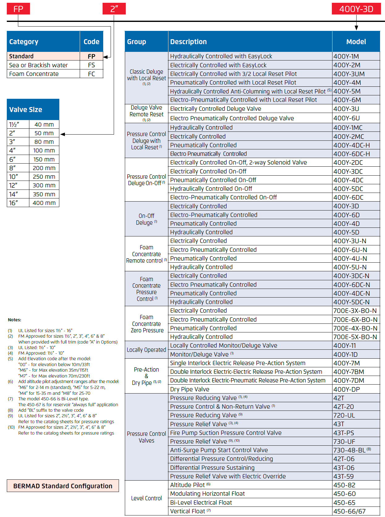
| Size Range: | 40-400mm |
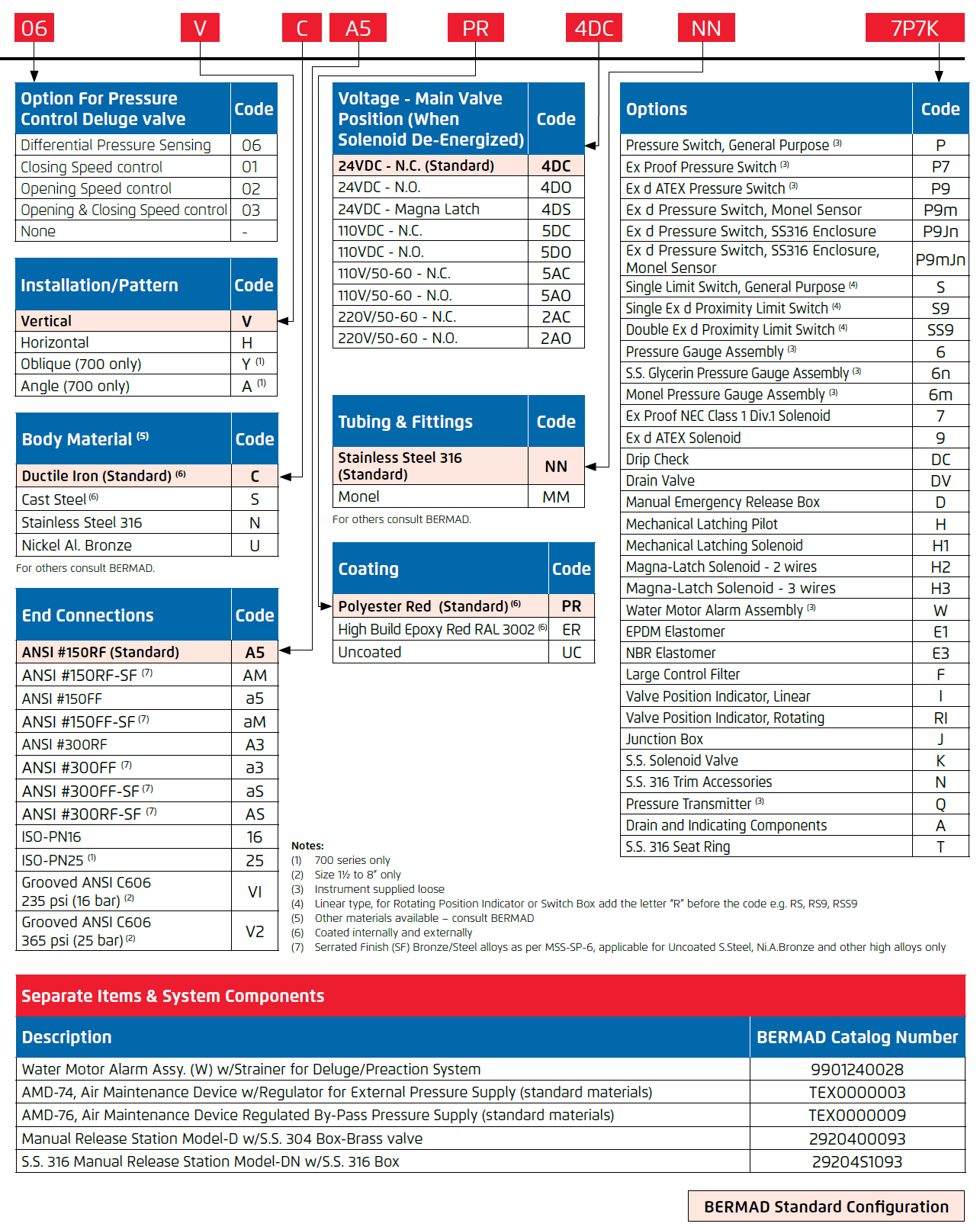
| Connection: | 40-400mm - Flanged |
Product Description
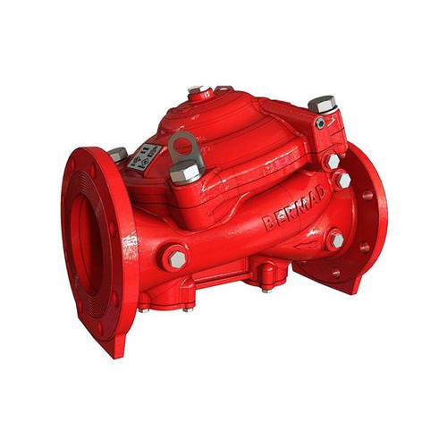
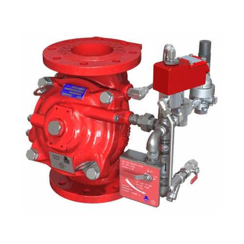
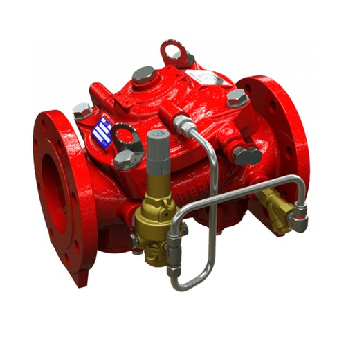
The BERMAD model 42T is an elastomeric, line pressure-driven pilot-operated pressure control valve, designed specifically for advanced fire protection systems and the latest industry standards. The 42T reduces high upstream pressure to a precise, preset, stable downstream pressure. Due to its exceptional reliability and low head loss the 42T is ideal for control of fire pump discharge. It is also well-suited to prevent over-pressure in sprinklers, hose stations, and other discharge devices. As an option, the 42T can be fitted with a valve position indicator that can include a limit switch.
Features and Benefits
- Safety and reliability
- Low head loss design - Increased safety at reduced pressure supply
- Time-proven, simple, fail-safe actuation
- Single-piece, rugged, elastomeric diaphragm seal - VRSD technology
- An Obstacle-free, uninterrupted flow path
- No mechanical moving parts
- High performance
- Fast, smooth stabilizing response to pressure fluctuations
- Very high flow efficiency
- Straight through Y-type body
- PN25/365 psi working pressure
- Specifically designed for fire protection
- Face-to-face length standardized to ISO 5752 EN 558-1
- Accurate and stabilizing pressure control
- Quick and easy maintenance
- In-line serviceable
- Fast and easy cover removal
Approvals

Additional Features
- Seawater compatibility
- Large control filter
- Integrated downstream relief valve
- Position limit switches
Typical Applications
- Sprinkler feed systems
- Fire pump discharge control
- Hose station supply
- Fire hydrant supply
- Foam systems
- Zonal pressure control
Technical Data
Operation
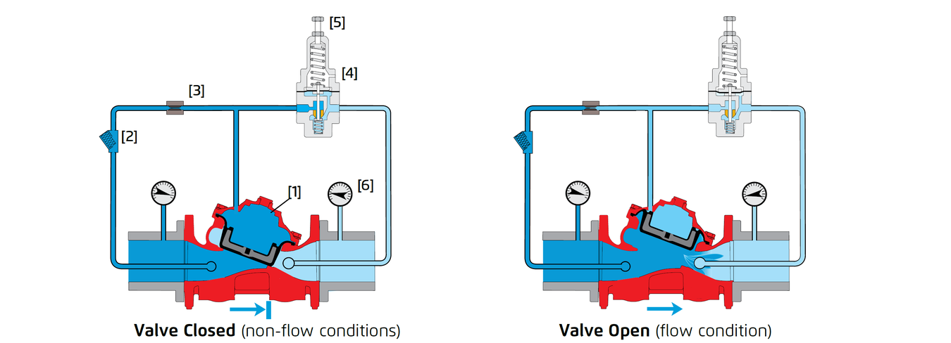
The BERMAD Model 42T pressure control valve, reduces water pressure automatically and accurately from a high inlet pressure to a lower, preset outlet pressure. The outlet set pressure can be adjusted by way of the pilot adjusting screw [5]. The valve operates under both flow and static conditions. The pressure-reducing pilot valve [4] senses changes in outlet pressure [6] and modulates the control valve to maintain the preset outlet pressure. When outlet pressure rises above the preset pressure, the pilot valve throttles, enabling pressure to accumulate in the control chamber [1], this causes the control valve to close further and reduce outlet pressure. When outlet pressure falls, the pilot valve opens wider, releasing pressure from the control chamber. This causes the control valve to open wider and increases outlet pressure. An integral restrictor [3] controls the valve’s closing speed. For valve sizes 12, 14 & 16” an adjustable needle valve is provided.
System P&ID
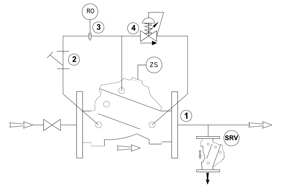
Components
1 BERMAD 400Y Water Control Valve
2 Y Strainer
3 Restriction Orifice
4 Pressure Reducing Pilot Valve
Optional System Items
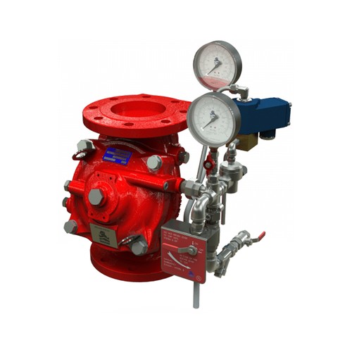
ZS Limit Switch Assembly
SRV BERMAD 43T Pressure Relief Valve
I Visual Indicator
Main Valve
Available Sizes and Connection
- 40-400mm - Flanged
- 40-200mm - Grooved
Pressure Rating
- ANSI#150: 17.2bar/250psi
- ANSI#300: 1½” to 10” 25bar/365psi, 12” to 16” 20bar/300psi (see note)
- Grooved: 1½” to 8” 25bar/365psi (see note)
- Threaded: 1½ & 2” - 25bar/365psi
Note: the 1½, 2 & 2½” valves are available with 28 bar/400 psi UL-Listed pressure rating
- Pilot Valves Model:
- #2PBL for 1½” to 10”
Pressure Setting Range: - UL-Listed: 4 - 12bar/60 - 175psi
- FM-Approved: 2 - 16bar/30 - 235psi
- #2PBL for 1½” to 10”
Elastomer
- HTNR - Fabric Reinforced High-Temperature Compound
System Installation
A typical installation of the BERMAD model 42T features a pilot valve for the automatic stable and accurate reduction of water pressure from a high upstream value to a preset lower downstream value, regardless of fluctuating upstream pressure or flow. A unique actuator design ensures quick and smooth valve action. Installed singly, the 42T provides a standard pressure-reducing system. Installed in parallel, two 42T valves provide high flow rates, redundancy, and zero downtime for maintenance. Installed in series, two 42T valves can provide a two-stage, high reduction in pressure and/or added protection to a reduced-pressure zone. To comply with the NFPA 13 and 14 standards and the UL/FM requirements, a listed pressure relief valve is to be installed on the downstream side of any pressure-reducing valve. For sizing the required relief valve for optimal performance see the BERMAD recommendation in the table below.

The BERMAD FP-3HC-0 and 43T Pressure Relief valves are ideally suited for this purpose, as shown in the installation illustrations.
Sprinkler System Pressure Reduction
- Reduces a high, unstable pressure supply to a preset, stable system pressure
- Sets the sprinkler pressure to suit the system design
- For zonal pressure control

Deeco - Bermad - FP-42T - Sprinkler System Pressure Reduction
Hose System Pressure Reduction
- Reduces a high/unstable pressure supply to suit fire hose pressure
- Limits fire hose pressure to 7 bar (100 psi) to meet NFPA 14 regulations for maximum allowable hose pressure supply

Deeco - Bermad - FP-42T - Hose System Pressure Reduction
Back-Up / Two-Stage Pressure Reduction
- Backup pressure reducing valve in-line to a master valve to secure pressure zone rating at all times. When in doubt consult BERMAD.

Deeco - Bermad - FP-42T - Back-Up Two-Stage Pressure Reduction
Parallel / Redundancy Pressure Reduction
- Recommended for a wide variation of flow rates. This arrangements enables high and low flow rates as well as providing a full pressure supply redundancy and serviceability with zero down time.

Deeco - Bermad - FP-42T - Parallel Redundancy Pressure Reduction
Technical Specifications
Engineering Specifications
The pressure-reducing valve shall maintain a constant, preset, downstream pressure regardless of fluctuating upstream pressure or flow, including static “no-flow” conditions, and shall operate with a minimum differential pressure of 0.4 bar / 5.8 psi between the inlet and outlet. The valve shall be UL listed and FM approved for 25 bar / 365 psi, line pressure driven and pilot operated. It shall be of the elastomeric type with a straight-through Y-type body. The cover and valve body shall be ductile iron to ASTM A536 GR 65-45-12 coated internally and externally with a high build corrosion resistant and UV protective epoxy coating. The valve shall have an unobstructed flow path with no stem guide or supporting ribs. Valve actuation shall be accomplished by a single-piece, rolling diaphragm bonded and strengthened by a rugged radial seal disc. The diaphragm unit shall be the only moving part. Maintenance, inspection, or service shall be carried out in line and without the removal of the control trim. The valve and its entire control trim shall be supplied pre-assembled and hydraulically tested by a factory certified to ISO 9000 and 9001 standards.
Dimensions and Weights


Notes:
(1) Refers to the length dimensions for Raised Face ANSI #150, ISO 16 Flanged, Threaded and Grooved valves
(2) Refers to the length dimensions for Raised Face ANSI #300 and ISO 25 Flanged valves
(3) Exact dimensions for the trim envelope may vary with specific component positioning
Due to the wide range of options and criteria for correct model selection, pricing and configuration are available on application only.
Please contact us for more information.

