| Brand: | Johnson Screens |
| Size Range: | Custom |
Product Description
Well screens are much more than a length of casing with a few slots into it. They rely on critical design parameters to perform the essential function of efficiently retaining the formation sand or gravel while allowing the maximum flow area for production.
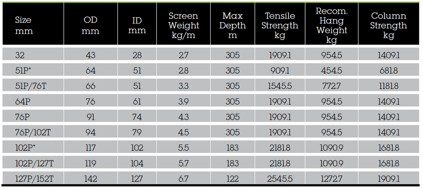
The continuous Vee-Wire® slot design allows for a lower entrance velocity of the water, reducing encrustation rates. The Vee-Wire® slot design also resists plugging and prevents sand from damaging pumps, while allowing minimal drawdown and less energy use to lift the formation fluids.
Features & Benefits
- Less maintenance: The continuous Vee-wire slot design allows for lower entrance velocity of the water, reducing encrustation rates. The slot design also resists plugging and prevents sand from damaging pumps.
- Pumping costs: The high open area of the vee-wire well screen allows for water to enter the well freely resulting in minimal drawdown and less energy usage by a pump.
- Sand control: The water well screen is a key component of the sand control system, either as an integral component of the gravel pack or as a stand-alone provider of sand control. Patented Vee-wire technology and welded construction help to prevent well screen failure by better controlling the sand.
- Designated for Optimal Performance:
- A technical representative of the Johnson Screens product line will analyze the formation sand and correctly size the well screen
- Proper grade of stainless steel for maximum corrosion resistance.
- Noting the depth of the well, the correct combination of wire and road produces a screen with all the necessary strength.
- Screen design is determined by aquifer characteristics and desired yield.
- Can provide all of the fittings, welded or threaded, that are needed for installation
Using a Johnson Screens Well Screen
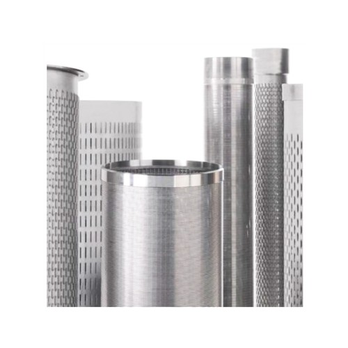
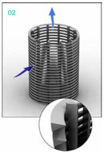
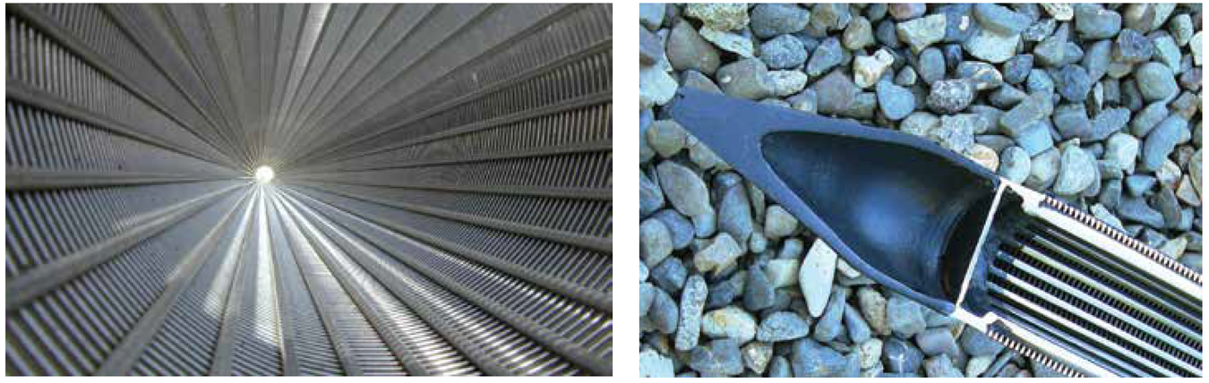
While screen designs offered some improvements, the Johnson Screens® well screen design revolutionized the industry.
Unlike other types of screens that are available, the Johnson Screens® design uses a series of support rods, around which a continuous length of V-shaped wire (Vee-Wire®) is wrapped. Each intersection of wire and rod is welded, making a very strong, cage-like cylinder with one continuous slot, spiraling along the full length of the well screen.
Pump Protection
Well-screen slots can be very narrow and precisely sized to keep out even fine sand grains, which could destroy a pump.
Lowering Pumping Costs
Even with very narrow slots, the total open area for the water to enter is far higher than other screen designs. This design allows for more water with lower pumping costs.
Longer Well Life
The slots widen inward, so sand grains do not wedge and plug. Screens can be constructed from stainless steel for maximum corrosion resistance. The high open area of a Johnson Screens® water well screen lets the water enter slowly, avoiding problems that can happen when water is pumped at high velocity. (If water passes into the screen too quickly, pressure drops and gases are released, allowing minerals to drop out of the solution and form encrustations on the screen surface. High-velocity water can also erode the screen, causing the slots to widen and allowing sand to enter the well.)
A More Efficient Well
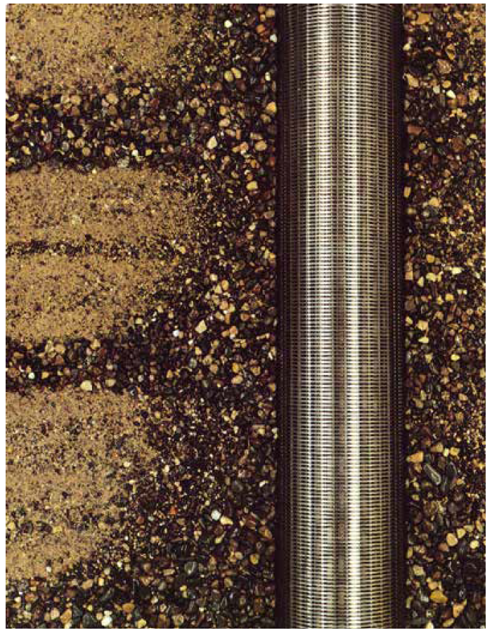
Part of well construction involves a process called well development, in which finer sand grains are pumped into the well and removed. By the end of the process, only the larger sand and gravel particles are left next to the well screen. Water then passes freely around these coarse particles and enters the well through the screen.
Remember, every drop of water from your well must first pass through the well screen. A Johnson Screens® water well screen is stronger, more plug-resistant, longer lasting, and more efficient than any other screen design available, resulting in more water for you, for a longer time and at less cost.
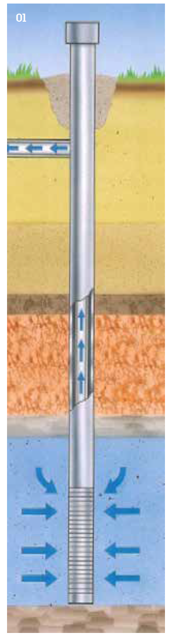
1 - Johnson Screens® allow thorough well development, which cleans out the finer particles around the screen and improves flow into the well.
2 - The Johnson Screens® Water Well screen keeps gravel out and lets water in.
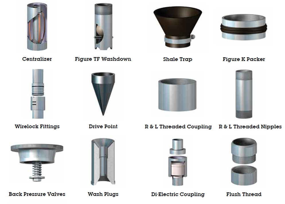
End Fitting & Screen Connection Options
The majority of well-screen installations involve at least a few standard fitting combinations.
Telescope-size screens typically use a figure K packer on the screen top and a welded or threaded plate bottom. Pipe-size screens attach directly to the casing and usually have plate bottoms.
Johnson screens stocks a variety of fittings, such as centralizers, shale traps, and connecting fittings for quick delivery.
Options include:
- Flush threads (Sch 40 and Sch 80)
- NPT threads
- Weld rings
- API couplers
- Plate bottom
- Threaded point
- Threaded cap/plugs
- Locking caps
- Bail hooks
Weld ring x weld ring - Weld ring x collar
- PVC to stainless steel adapter
- Quickloc
- Shur-A-Lock
The Johnson Screens Di-Electric Coupling Prevents Galvanic Corrosion in Municipal and Industrial Water Well Completions
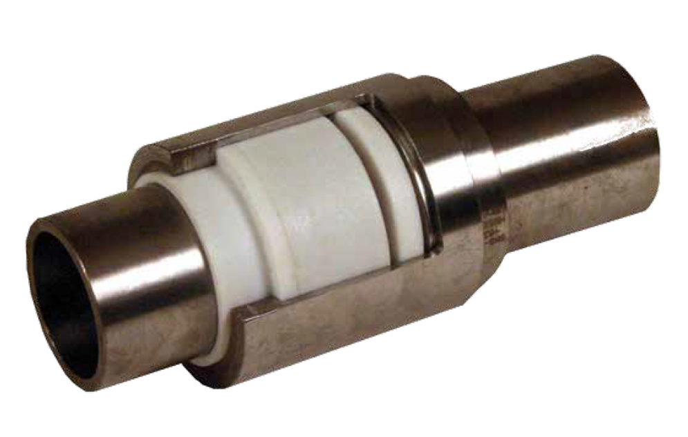
When two dissimilar metals are coupled in water-saturated environments, the less corrosion-resistant metal corrodes faster from the galvanic cell created. This corrosion can be prevented by eliminating the contact between the two metal surfaces.
A di-electric coupling uses insulating rings that separate the metals and prevents contact. This feature increases the life of the pipe and the life of the well. Di-electric couplings are available for pipe sizes from 38 to 609 mm (15-24 in.). Special sizes or connection adaptors are available upon request.
Advantages, features, and benefits
- In the center of the coupling, an insulating sleeve prevents dissimilar metals from making contact and causing corrosion of the casing. This feature extends the life of the pipe for long-term savings.
- the coupling has a small OD, only 38 to 51mm (15 to 2in) larger than the pipe. This feature saves costs by minimizing the size of the hole to be drilled.
- The nominal ID of the string is maintained through the coupling for full design functionality.
Technical Data
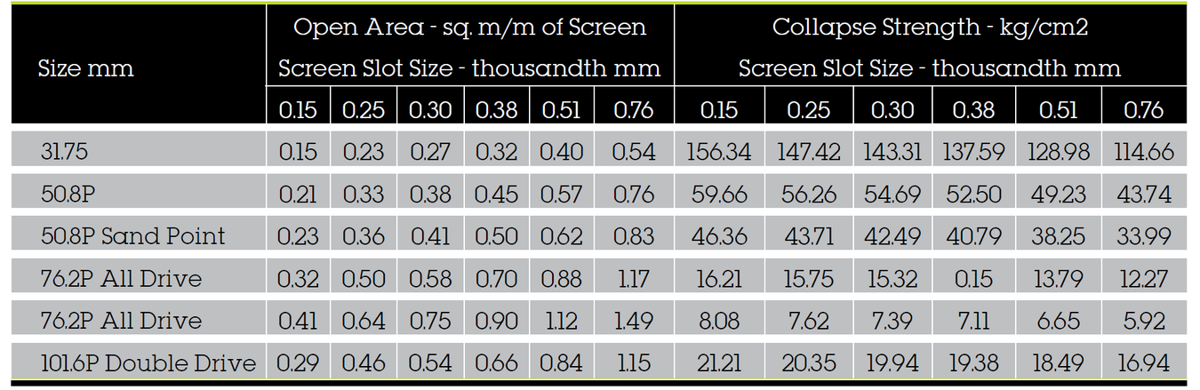
Model 60-Wire - 304 and 316 Stainless Steel
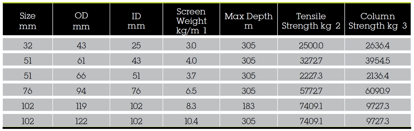
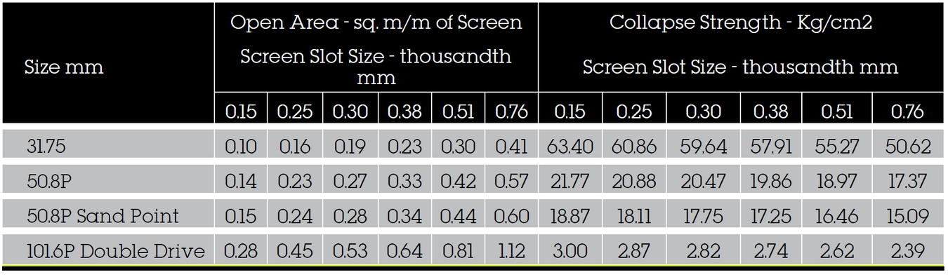
Model 90-Wire - 304 and 316 Stainless Steel
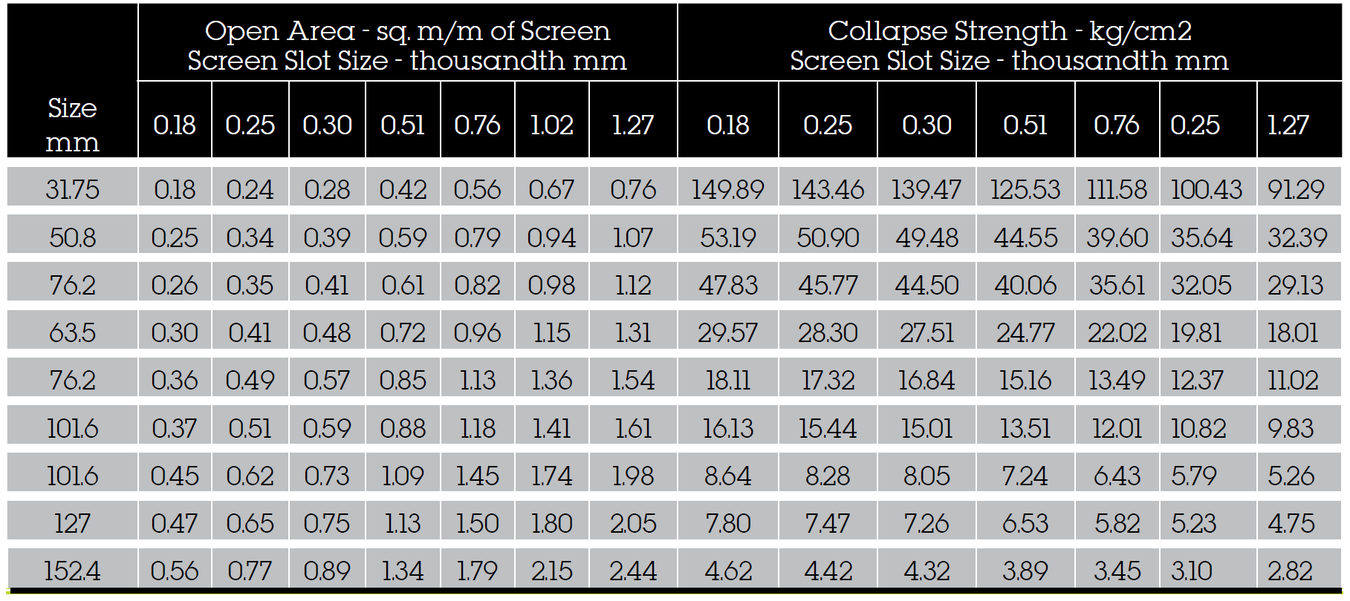
Notes:
- Transmitting capacity (lpm/m. of screen) = open area x 0.31 @ 30mm/sec
- P - pipe size
- Weight is based on 10-slot construction, no fittings
- Tensile and column strength includes a 30 percent safety factor
- Column strength is based on 15m screen barrel length
- Calculated collapse values - no safety factor included
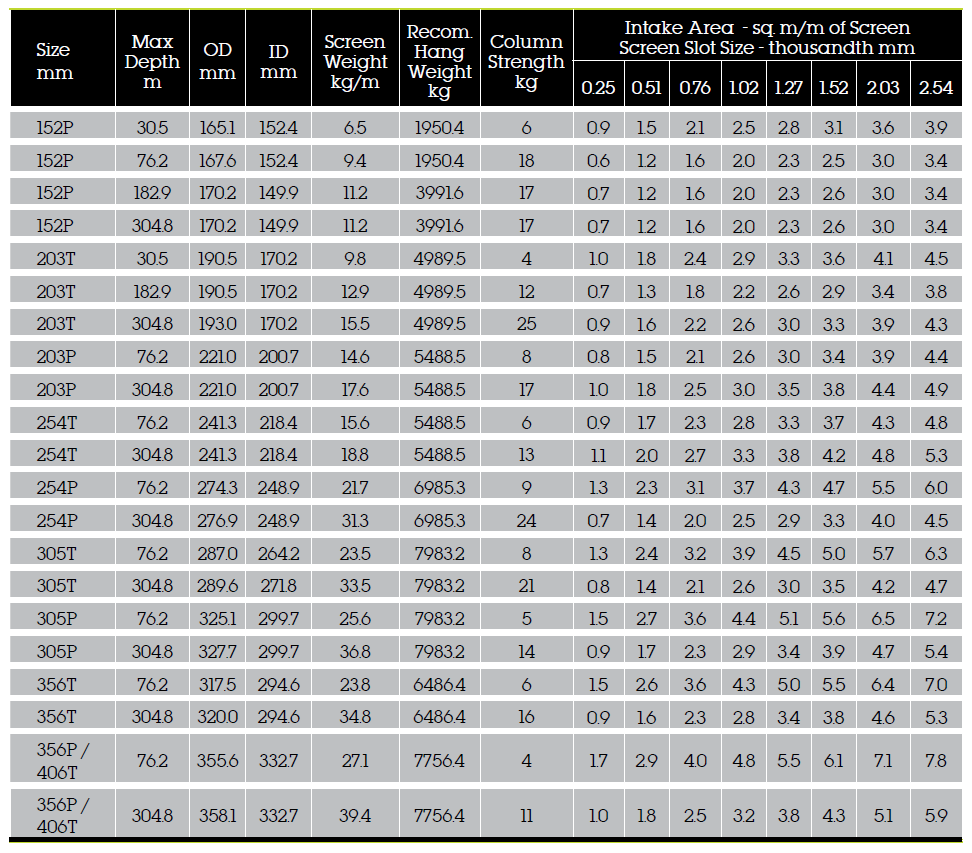
Water Well and Environmental Screens: 60 Wire Construction 304 and 316 Stainless Steel
Water Well and Environmental Screens: 90 Wire Construction 304 and 316 Stainless Steel
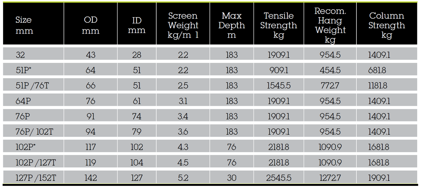
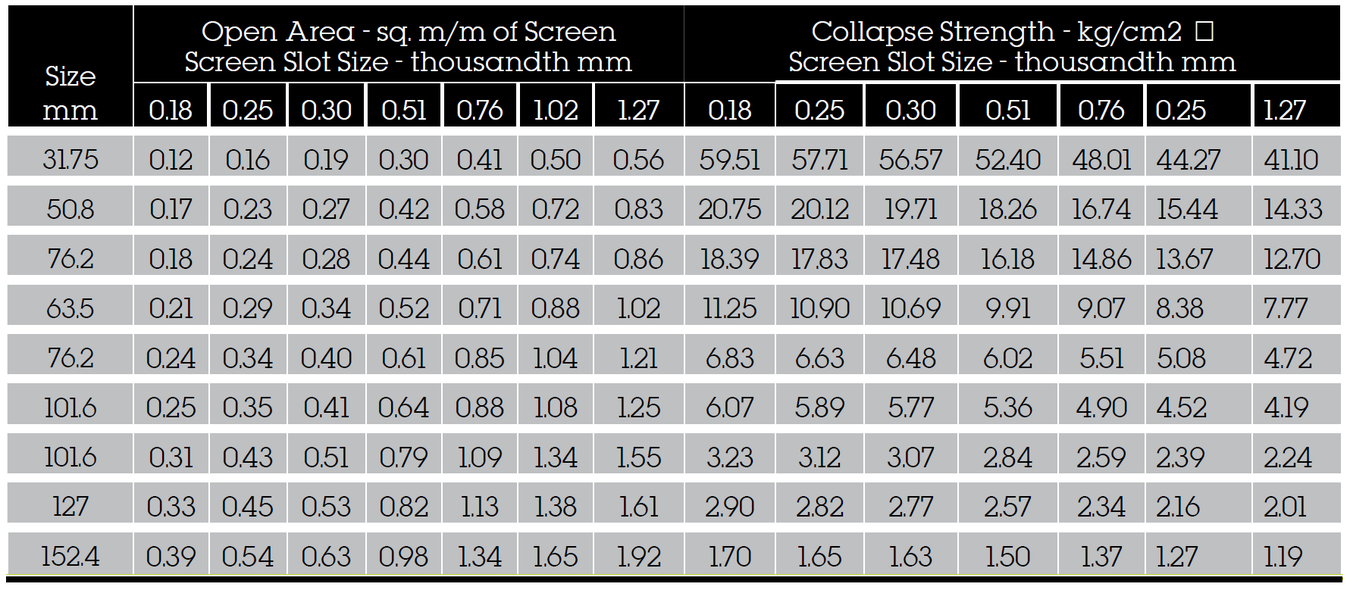
Notes:
- Transmitting capacity (lpm/m. of screen) = open area x 0.31 @ 30mm/sec
- P - pipe size, T - telescope
- Weight is based on 10-slot construction, with no fittings
- Tensile and column strength includes a 30 percent safety factor
- The recommended hang weight is 50 percent of the calculated tensile strength
- Column strength is based on a 1.5m screen barrel length
- Calculated collapse values - no safety factor included
*Alternate constructions for water well and environmental
**ID confirmed clear for environmental with Sch 40 fittings only (Sch 80 is smaller)
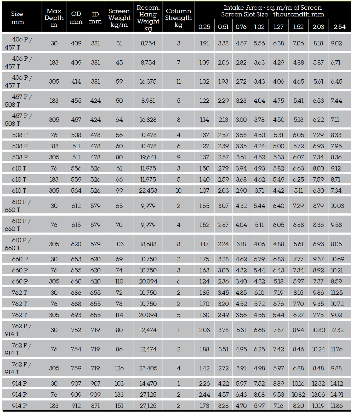
Water Well and Environmental Screens: 60 Wire Construction 304 and 316 Stainless Steel
Notes:
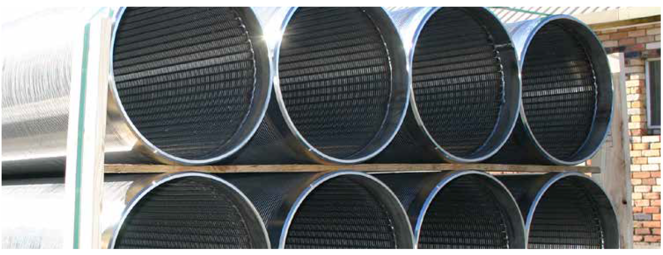
- Screens are available in up to 12m lengths of continuously wrapped screen with no mid-weld
- 315 stainless steel screen technical information is available upon request
- P - pipe size, T - telescope
- Based on 0.8mm slot size (collapse values contain no safety factor)
- Recommended hang weight is 50 percent of the calculated tensile strength
- transmitting capacity (lpm/m of screen) = open area x 0.31@ 30mm/sec
Large Diameter Free-Flow Screens: Sizes 406T - 914P
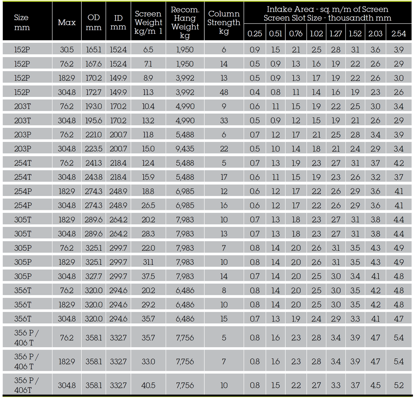
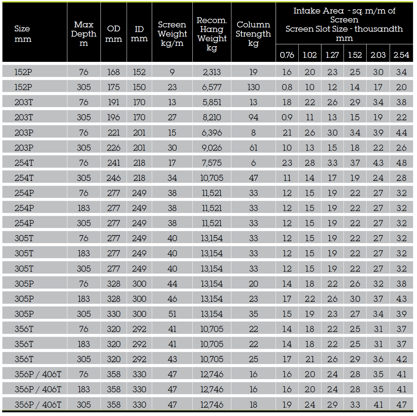
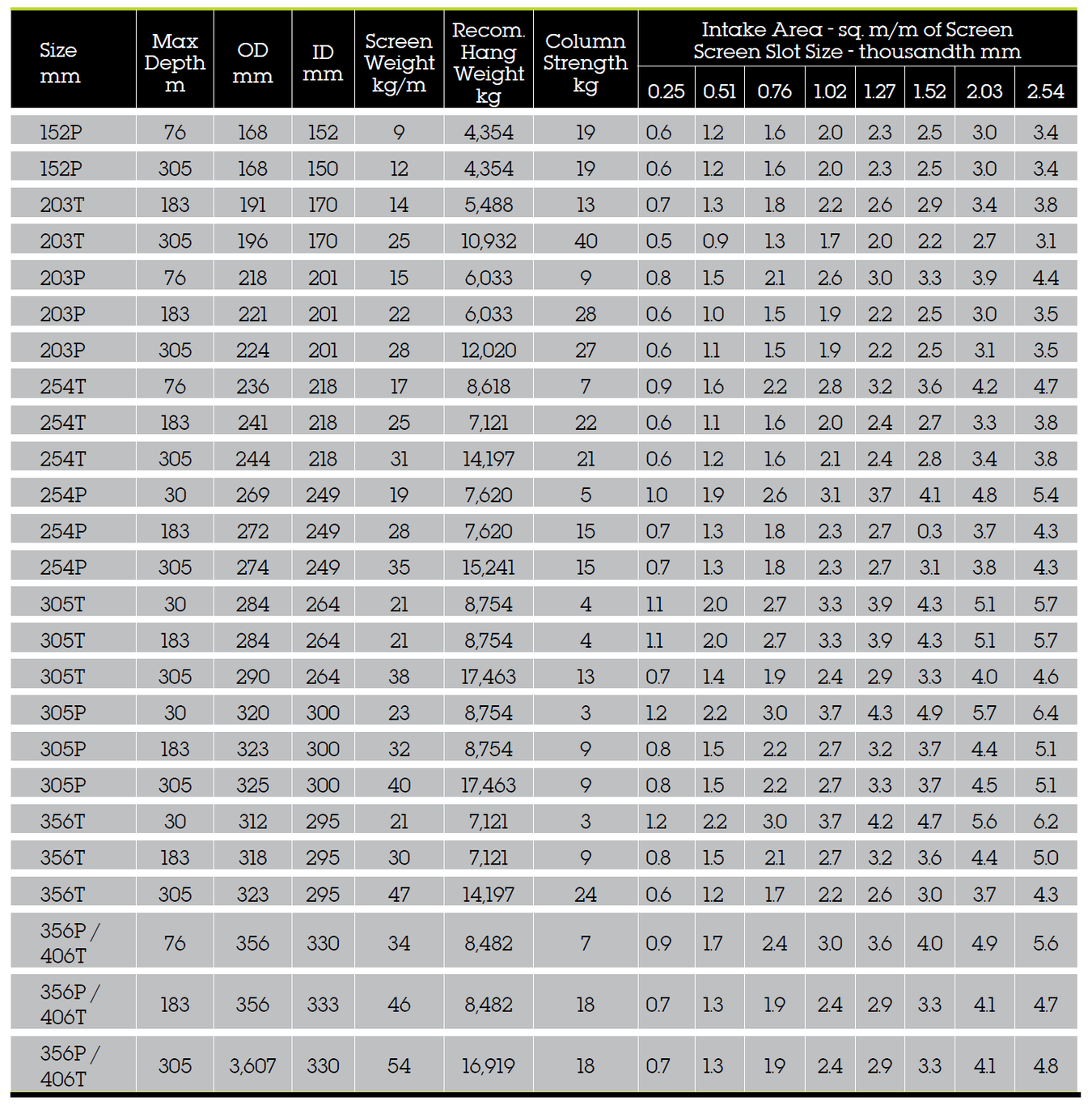
Large Diameter Hi-Flow Screens: Sizes 152P - 406T
Notes:
- Screens are available in up to 12 m lengths of continuously wrapped screen with no mid-weld.
- 315 stainless steel screen technical information is available upon request.
- P - pipe size, T - telescope
- Based on 0.8mm slot size (collapse values contain no safety factor).
- Recommended hang weight is 50 percent of the calculated tensile strength.
- Transmitting capacity (lpm/m of screen) = open area x 0.31 @ 30 mm/sec.
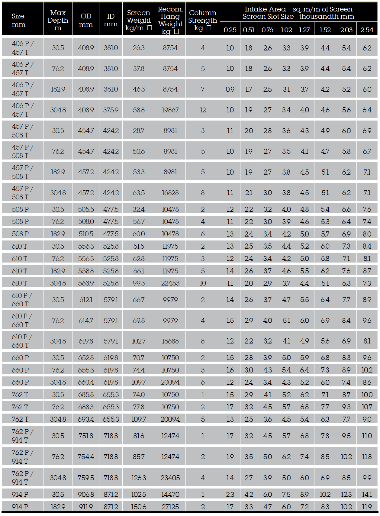
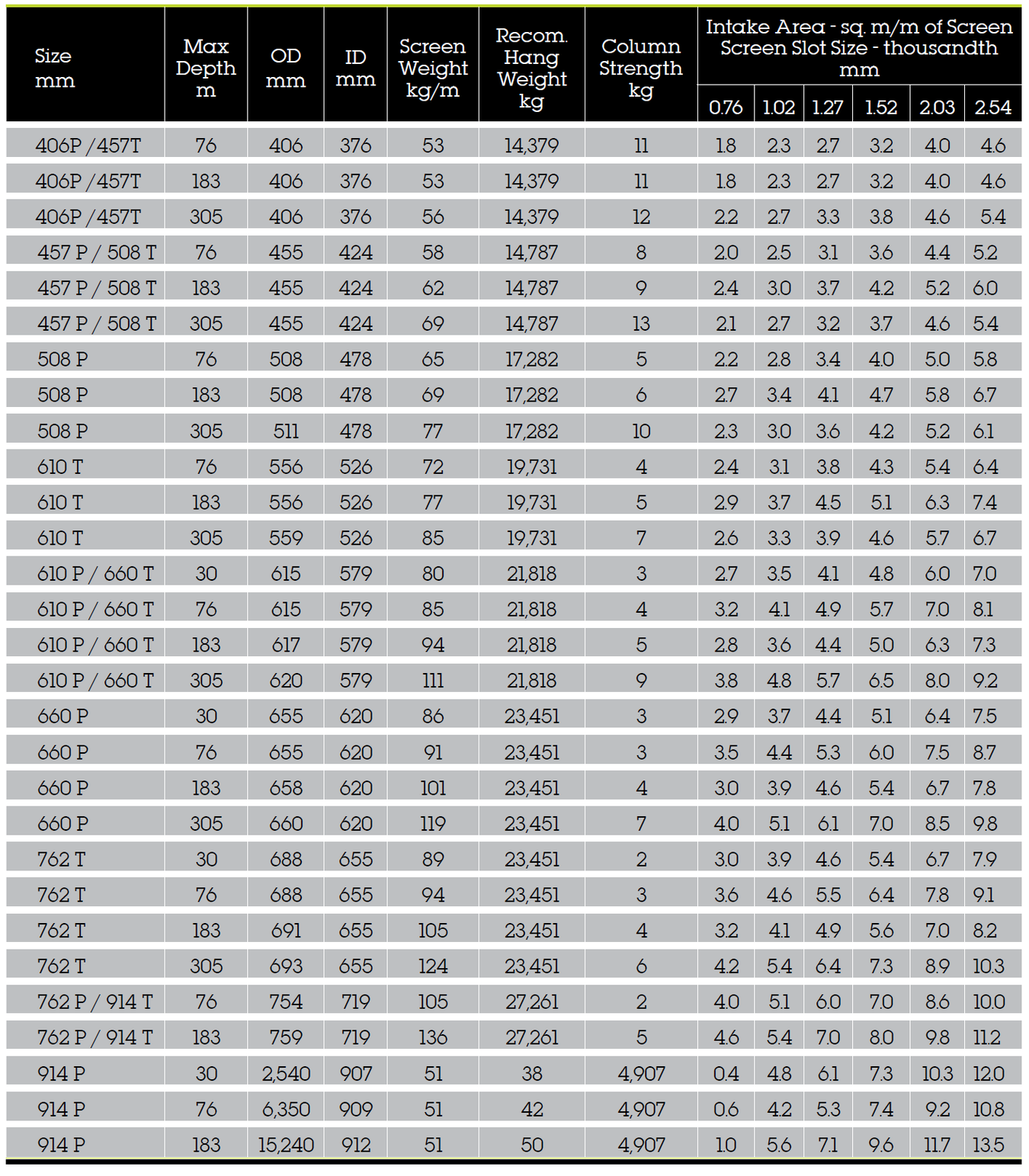
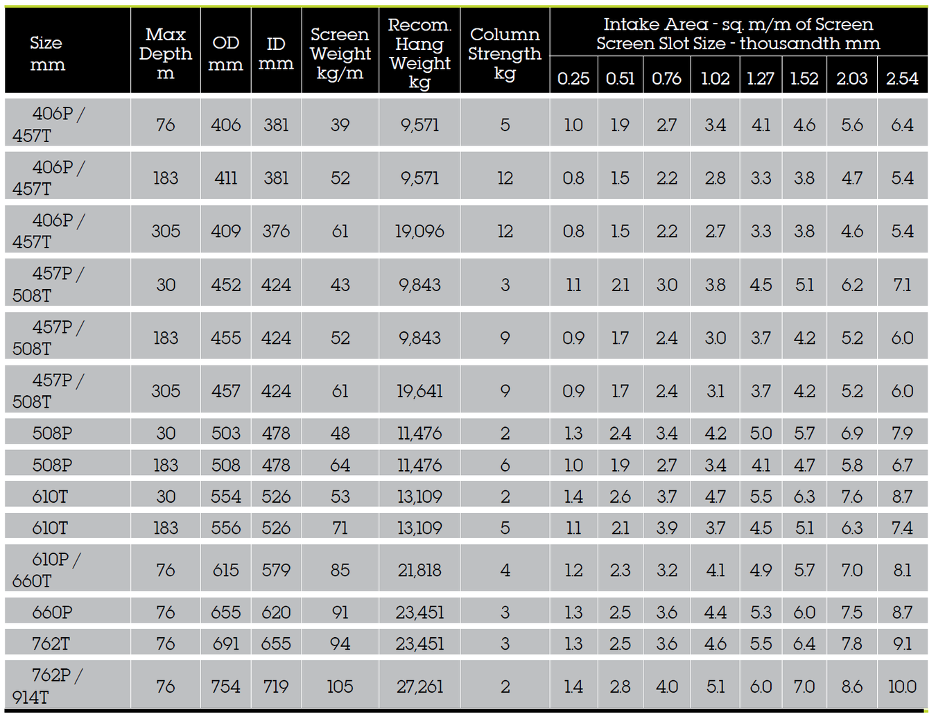
Large Diameter Hi-Flow Screens: Sizes 406P - 914P
Large Diameter Hicap Screens: Sizes 152P - 406T
Notes:
- Screens are available in up to 12 m lengths of continuously wrapped screen with no mid-weld
- 315 stainless steel screen technical information is available upon request
- P - pipe size, T - telescope
- Based on 0.8mm slot size (collapse values contain no safety factor)
- The recommended hang weight is 50 percent of the calculated tensile strength.
- Transmitting capacity (lpm/m of screen) = open area x 0.31 @ 30 mm/sec
Large Diameter Hicap Screens: Sizes 406P - 914T
Large Diameter Hicap Screens: Sizes 152P - 406T
Large Diameter Hicap Screens: Sizes 406P - 914T
Notes:
- Screens are available in up to 12 m lengths of continuously wrapped screen with no mid-weld.
- P - pipe size, T - telescope
- Based on 0.8 mm slot size (collapse values contain no safety factor)
- Recommended hang weight is 50 percent of the calculated tensile strength
- Transmitting capacity (lpm/m. of screen) = open area x 0.31 @ 30 mm/sec
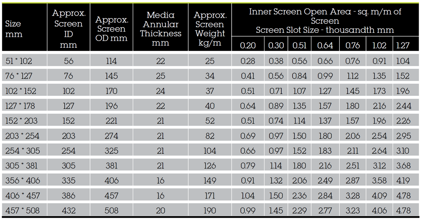
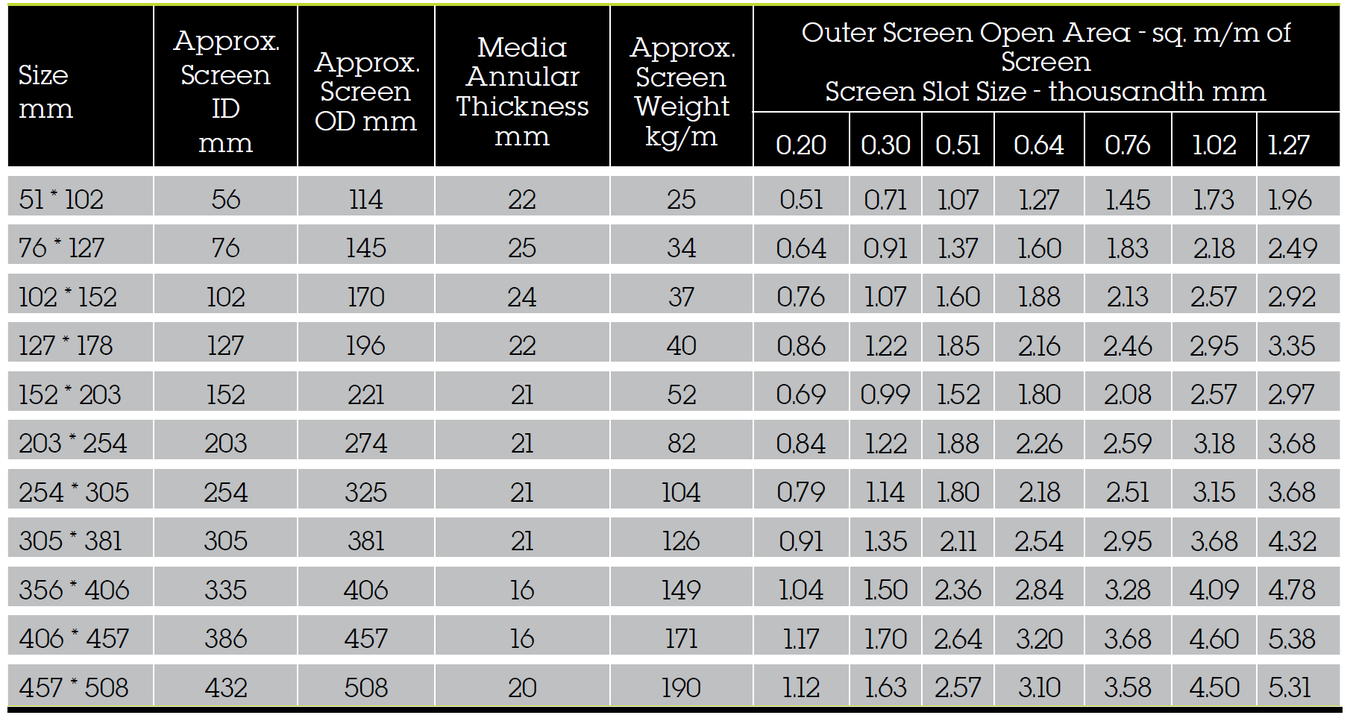
Muni-Pak™ Screen Specifications
Muni-Pak™ screens are pre-packed, providing numerous features and advantages for the contractor and well owner. A smaller borehole, stronger construction, thinner filter pack and maximized open area all combine for an energy and time saving well screen.
Muni-Pak™ Screen vs. Standard Rod Based Screen
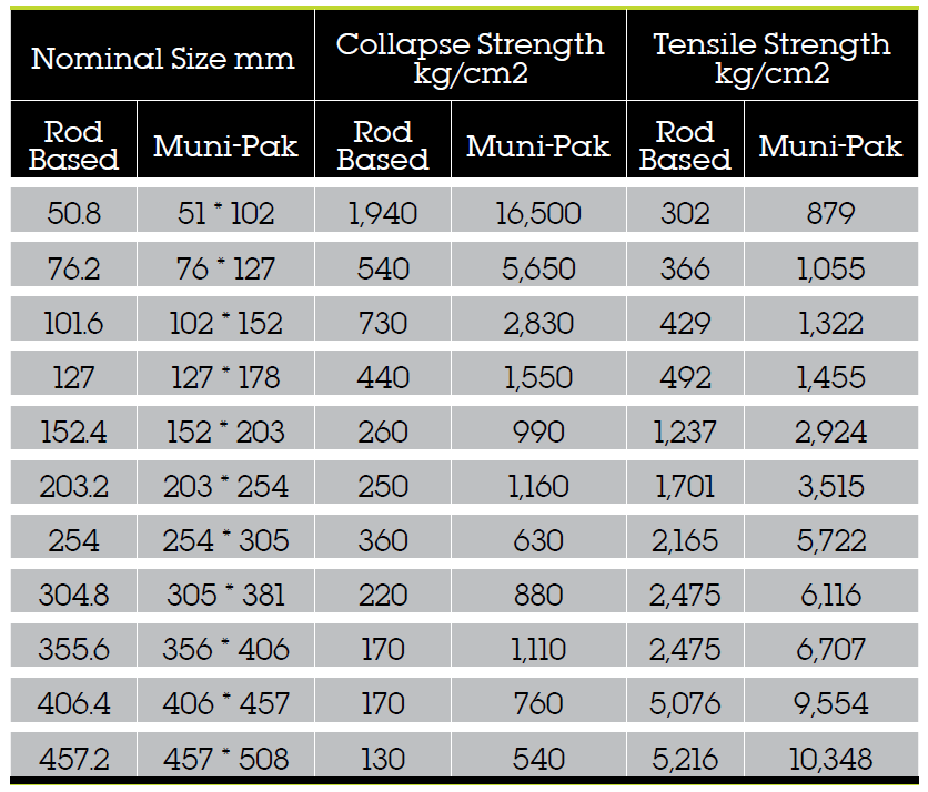
Standard Filter Pack Sizes
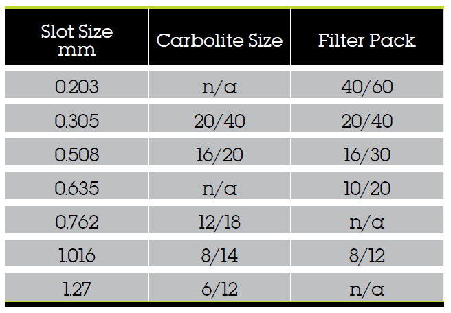
Notes:
- Other sizes are available upon request
- Values compare 305m of Muni-Pak™ vs 305 m of rod-based screen
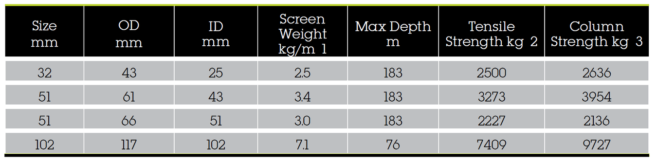
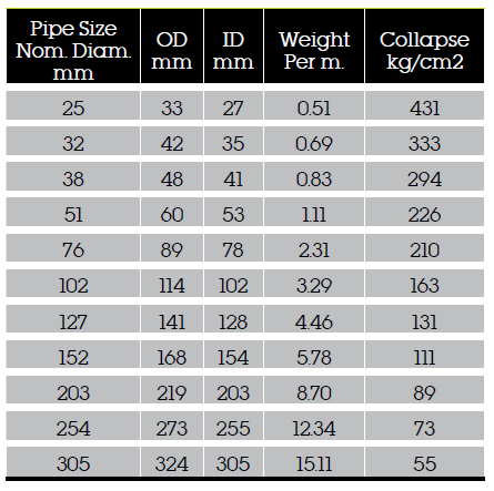
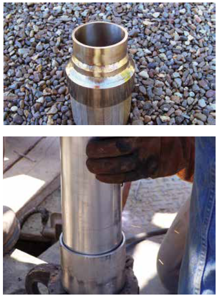
Stainless Steel Pipe Based Well Screens
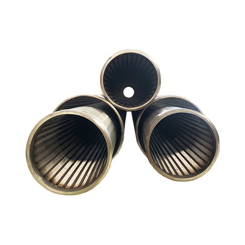
Pipe-based well screens combine the hydraulic efficiency of wire-wound screens with the strength of the pipe. Because of the strength of the pipe liner, the wrap wires can be smaller, producing a greater open area.
the longitudinal support rods on the screen jacket create channels that direct incoming flow to the nearest pipe perforation. Screen and pipe are welded to make a rugged, reliable until suitable for deep vertical wells and supply wells.
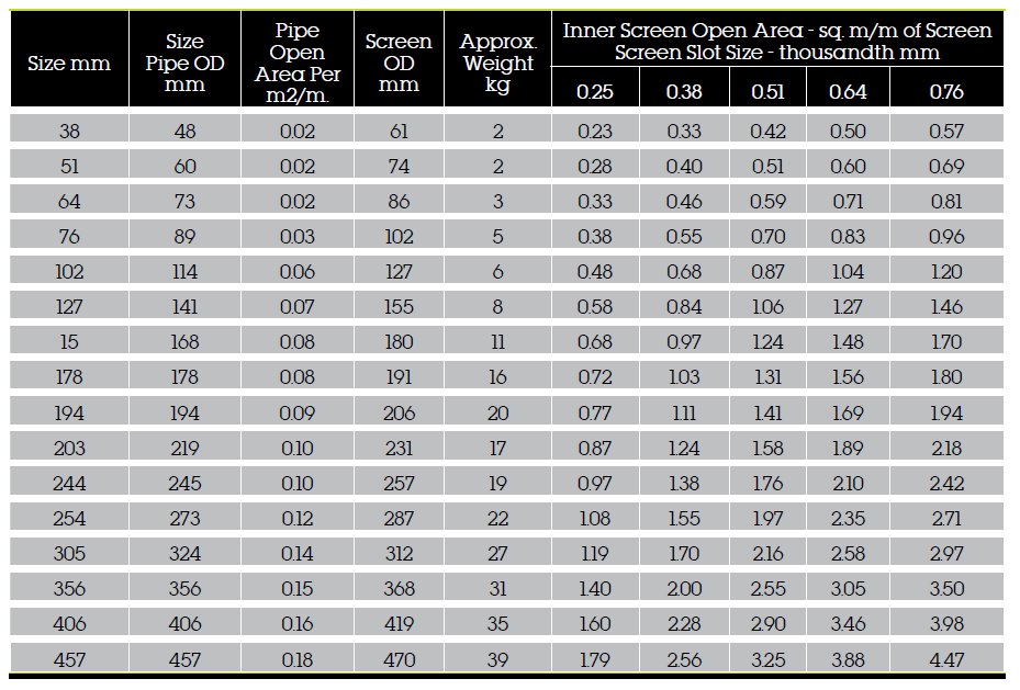
Note: Weight is based on the standard well pipe, except for 194mm.
304 Stainless Steel Casings
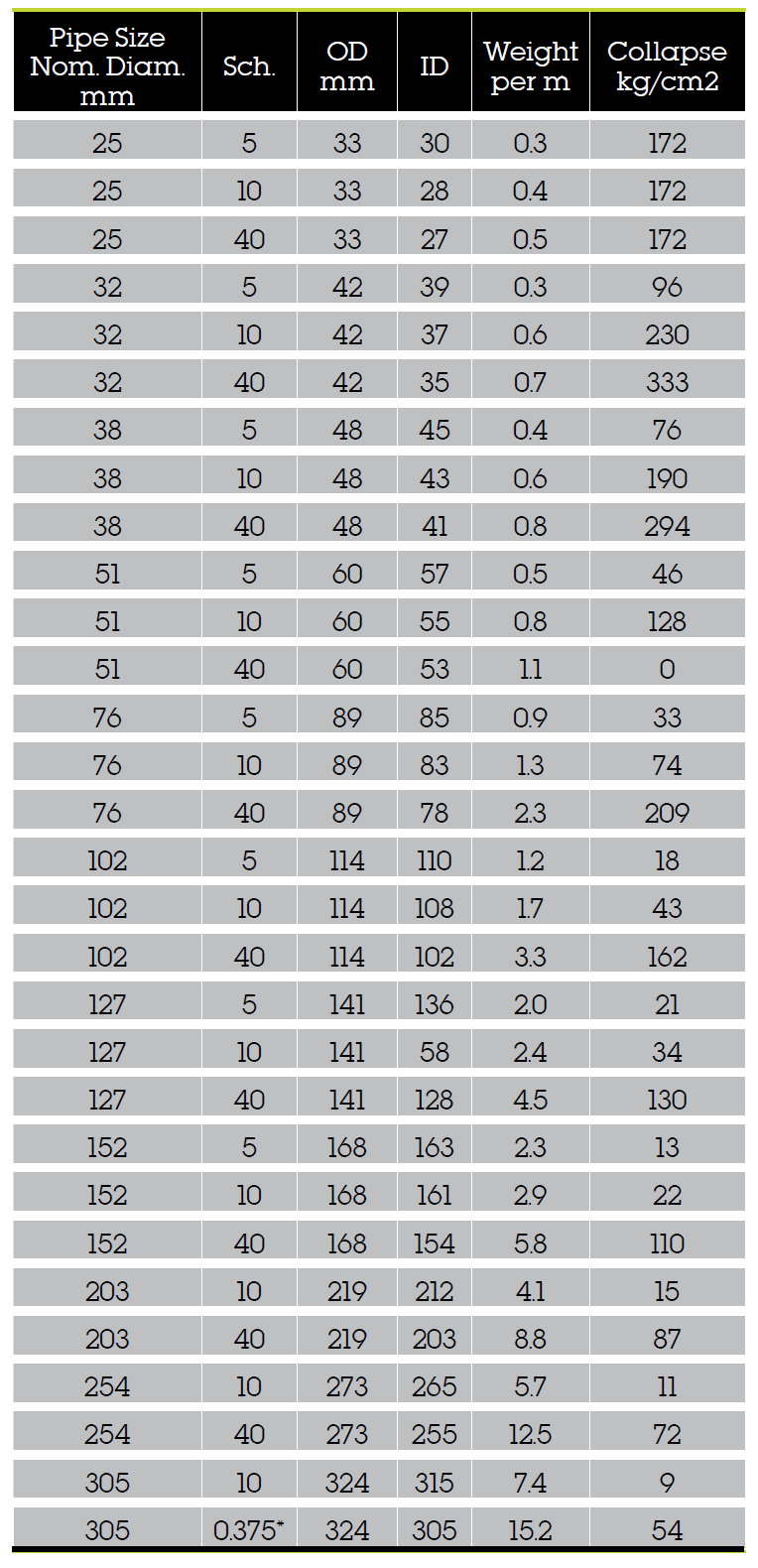
SCH 40 Low Carbon Steel Casing
Technical Specifications
General: Well screens shall be of the continuous slot design to provide maximum open area, reduce entrance velocity, increase hydraulic efficiency, and promote more effective development. The well screens shall be constructed of Vee-Wire® trapezoidal wire, continuously wrapped around an array of equally spaced support rods of the same material. Each junction of wire/rod contact shall be resistance welded. The screens and end fittings shall be made of __________ (material). The well screens shall be manufactured by Bilfinger Water Technologies or an approved equal.
Collapse strength: Well screens shall be _________________ millimeters OD, continuous slot wire-wrapped __________ (material), designed to withstand a minimum collapse pressure of ______ kg/ cm2 for a _____ millimeter slot opening. The surface wire shape shall cause the slot opening to widen inwardly to minimize clogging. Surface wrap-wire height shall be _____ millimeters to provide the desired collapse strength. The wrap-wire face width shall be of minimum dimensions to provide _____ percent open area at the anticipated _____ millimeter slot opening.
Tensile strength: The minimum screen tensile strength must exceed at least twice the total weight of the screen and any standard wall blank casing suspended below the top screen joint. The tensile strength shall be a minimum of _____ kilograms. (Tensile strength is total rod area times material yield strength.) Screen configuration: Screens shall be manufactured in various lengths complete with __________ (material) weld rings attached to each end. The weld rings shall be standard available lengths as requested by the contractor and approved by the engineer.
General: Muni-Pak™ screens shall be of the continuous slot design to provide maximum open area, reduce entrance velocity, increase hydraulic efficiency, and promote more effective development. Both the inner and outer screens shall be constructed out of Vee- Wire® traezoidal wire, continuously wrapped around an array of equally spaced support rods of the same material. Each junction of wire/rod contact shall be resistance welded. The screens and end fittings shall be made of __________ (material). The well screens shall be manufactured by Bilfinger Water Technologies or approved equal.
Diameter: The Muni-Pak™ screen shall be _____ millimeter pipe size inner screen by _____ millimeter pipe size outer screen
Collapse: The dual screen assembly shall be manufactured with a wrap-wire designed to yield a minimum collapse pressure of _____ kg/cm2 at a design slot opening of _____ millimeters. The wire shape shall cause the slot opening to widen inwardly to minimize clogging.
Open area: The inner screen shall provide _____ square mllimeters of inlet area per foot of the screen at the design slot size. The outer screen shall be in the same slot as the inner screen. The slot size and filter pack are to be selected on the basis of a sieve analysis of the water-bearing formation.
Filter pack: The annulus between screens shall be filled with ceramic or glass beads of uniform size and excellent sphericity. The pack size shall be _____ filter size. The pack material shall be installed and compacted by vibrating the unit in a vertical position while being filled. The top and bottom filter seal plates shall be secured by welding.
Tensile strength: The minimum screen tensile strength must exceed at least twice the total hang weight of the screen and blank casing below the top screen joint. The tensile strength shall be a minimum of ___ kilograms. (Tensile strength is total rod area times material yield strength).
Screen configuration: Screens shall be manufactured in various lengths with a maximum of 12 meters length overall. Screens shall be complete with _____ (material) and fittings attached to each end. Standard weld rings are 152 millimeters long on each end. Weld rings of longer lengths, or threaded fittings may be requested. Screen barrels shall be provided in standard _____ (overall or full) lengths which _____ (include or exclude) the weld ring lengths.
Due to the wide range of options and criteria for correct model selection, pricing and configuration are available on application only.
Please contact us for more information.