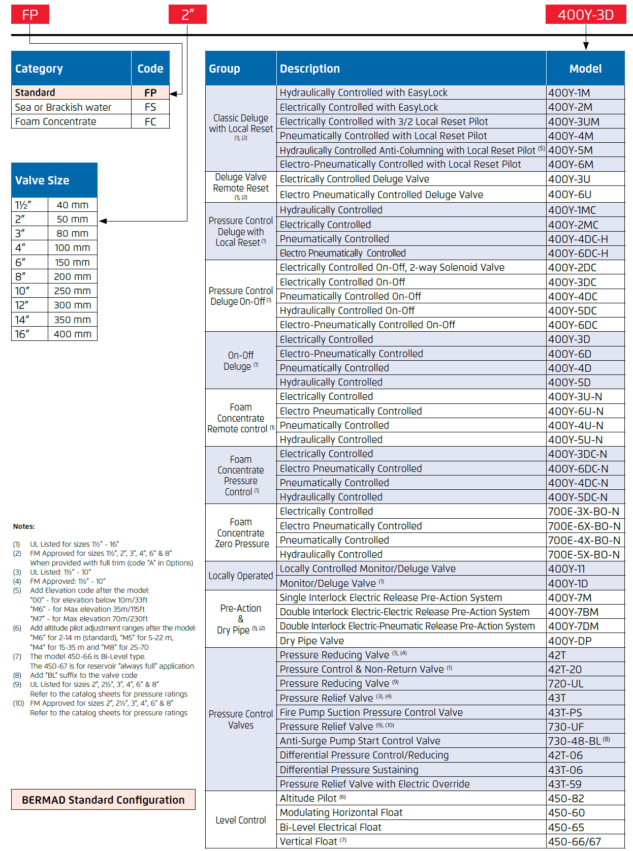
| Brand: | Bermad |
| Category: | Control Valves, Fire Protection Series |
| Engineering Data: | |
| Size Range: | 50-400mm |
| Connection: | 50 - 300mm - Flanged 80 - 200mm - Grooved |
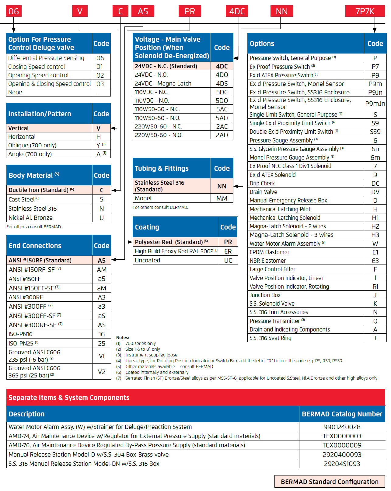
Product Description
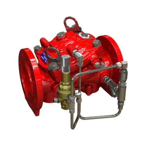
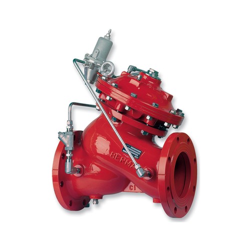
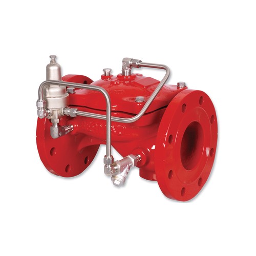
The BERMAD Model FP 430-UF pilot operated valve prevents over pressure, maintaining a constant preset system pressure regardless of fluctuating demands. UL-Listed (up to 175 psi) and FM-Approved according to NFPA-20. The valve offers reliable performance in: Refineries, petrochemical complexes, tank farms, high-rise buildings, aviation, marine and on-shore installations.
Features and Benefits
- Advanced Elastomeric Globe type –Low-pressure loss
- One-piece molded elastomeric moving part – No maintenance required
- Simple design –Cost-effective
- In-line serviceable – Minimal downtime
Optional Features
- Large control filter (code: F)
- Seawater service construction
- Valve Position Single/Double Limit Switches
Note: Optional features can be mixed and matched. Consult Deeco for more details.
Approvals

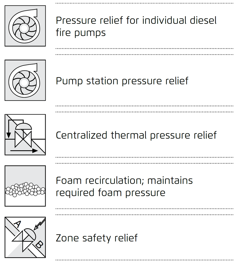
Typical Applications
Technical Data
Operation
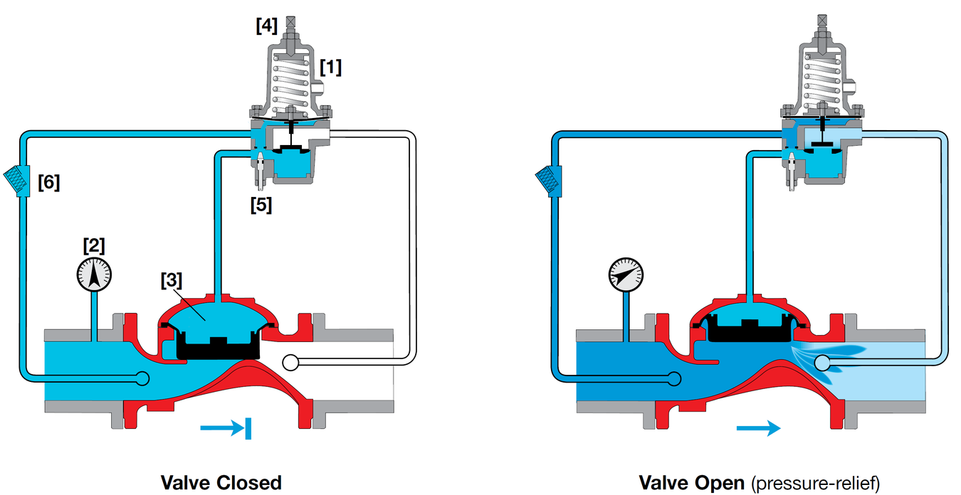
The BERMAD Model FP 430-UF remains closed if the sensed upstream pressure is lower than the adjustable set point. When the Pressure Relief Pilot [1] senses upstream pressure [2] that is higher than the pilot setting, it acts upon the control chamber [3] causing the main valve to modulate open, relieving excess pressure to either a reservoir or sump, thus preventing system overpressure. The Pressure Relief Pilot is equipped with an adjusting screw [4] to preset the desired upstream pressure, and an integral adjustable needle valve [5] to control the main valve closing speed. The valve’s unique design quickly reacts to system demand and keeps pressure loss at a minimum. The control system is equipped with a control strainer [6].
Manufacturers Standard Materials
Main valve body and cover
- Ductile Iron ASTM A-536
Main valve internals
- Stainless Steel & Elastomer
Control Trim System
- Brass control components/accessories
- Stainless Steel 316 tubing & fittings
Elastomers
- Polyamide fabric reinforced Polyisoprene, NR
Coating
- Electrostatic Powder Coating Polyester, Red (RAL 3002)
Optional Materials
Main valve body
- Carbon Steel ASTM A-216 WCB
- Stainless Steel 316
- Ni-Al-Bronze ASTM B-148
Control Trim
- Stainless Steel 316
- Monel® and Al-Bronze
- Hastelloy C-276
Elastomers
- NBR
- EPDM
Coating
- High Build Epoxy Fusion-Bonded
with UV Protection, Anti-Corrosion
Main Valve
Connection Standard
- Flanged: ANSI B16.42 (Ductile Iron),
B16.5 (Steel & Stainless Steel),
B16.24 (Bronze)
- ISO PN16
- Threaded: NPT or ISO-7-Rp for 2, 2½ & 3”
- Grooved: ANSI/AWWA C606 for 2, 3, 4, 6 & 8”
Water Temperature
- 0.5 – 50°C (33 – 122°F)
Available Sizes
- Globe: 2, 2½, 3, 4, 6, 8, 10 & 12”
- UL Listed and FM approved: 2, 2½, 3, 4 & 6”
UL Listed / FM Pressure Rating
- Max. inlet: 175 psi (12 bar)
- Set: 30 - 175 psi (2 - 12 bar)
- Test: 365 psi (25 bar)
Technical Specifications
Engineer Specifications
The Pressure Relief Valve shall be Ul-listed, FM-Approved, and hydraulic pilot controlled. The main valve shall be an elastomeric-type globe valve with a rolling diaphragm.
Valve actuation shall be accomplished by a fully peripherally supported, one-piece balanced rolling diaphragm, vulcanized with a rugged radial seal disk. The diaphragm assembly shall be the only moving part.
The valve shall have an unobstructed flow path, with no stem guide or supporting ribs.
The valve shall have a removable cover for quick in-line service enabling all necessary inspection and servicing.
The pilot system shall be field adjustable, with adjustable valve closing speed integrated into the main valve,
hydraulically tested and supplied as an assembly consisting of:
- Relief pilot valve UL-Listed and FM-Approved as part of the assembly with built-in, internal needle valve
- “Y” strainer
The control trim shall be supplied as an assembly, pre-assembled, and hydraulically tested at an ISO 9000 and 9001-certified factory.
Typical Installation
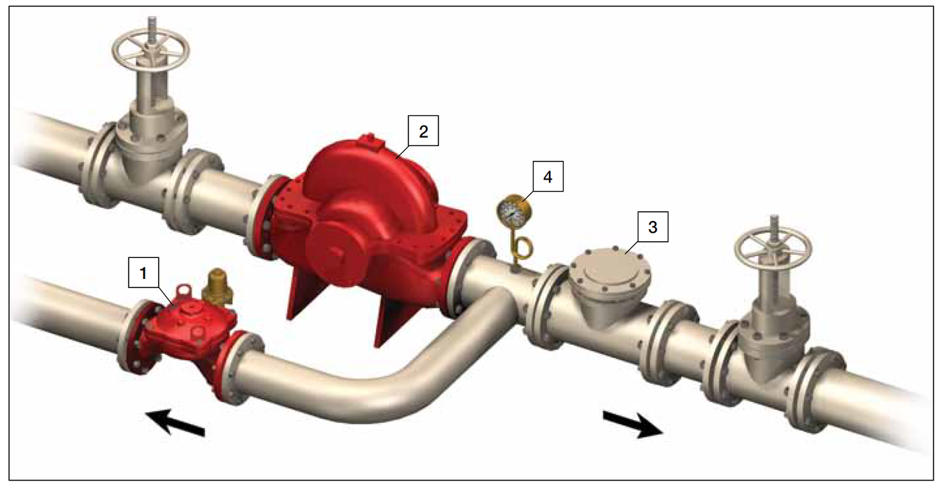
System Components
- BERMAD Model FP 430-UF
- Fire Pump
- Check Valve
- Pressure Gauge
Installation Considerations
- Valve size should be no less than NFPA-20 requirements.
- Provide adequate clearance around valve for maintenance, ensuring that the actuator can be easily removed.
- Design installation with the valve cover up for best performance.
- Ensure that before the valve is installed, instructions are given to flush the pipeline at full flow.
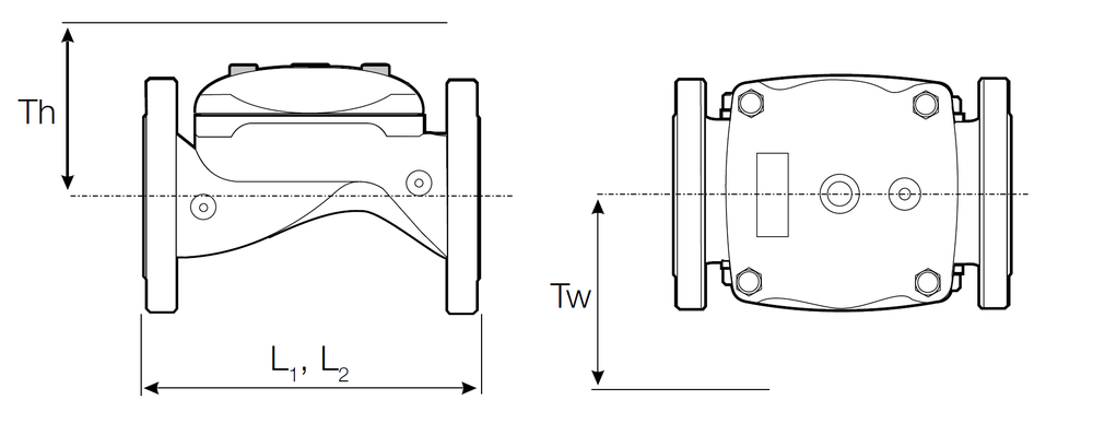
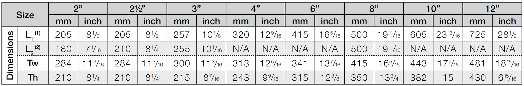
Dimensions and Weights
Due to the wide range of options and criteria for correct model selection, pricing and configuration are available on application only.
Please contact us for more information.