| Brand: | Talgil |
| Category: | Irrigation-Automation, RTUs - Remote Terminal Units , Analog, Digital & SDI Sensors |
Product Descriptions
The LIN Expansion series extends the capabilities of the Talgil Modular RTU and DREAM2 controller, offering flexible I/O options to meet a wide range of field application needs.
Compatible with RTU RF G5 (in G5 FAST mode) and DREAM2 Controllers, LIN cards connect via the dedicated LIN Port and support both parallel connection and automatic detection by the Master unit.
Each LIN card must be assigned a unique address when multiple cards of the same type are used. The Modular RTU auto-detects the card type and address, seamlessly integrating the data into the system.
Power Requirements:
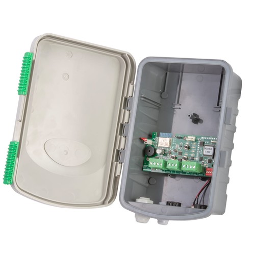
When using a LIN Expansion with the Modular RTU, a 12V DC power supply is required. Connect the rechargeable battery to the BATTERY input on the power supply plug. Charging is supported via an 18V DC source (solar panel or power supply) connected to the CHARGE input.
Available LIN Expansion Models
At this stage - the following LIN Expansion Models are available:
- 4 ANA LIN (4 ANALOG INPUTS)
- 840 LIN (8 OUTPUTS / 4 DIGITAL INPUTS / 0 ANALOG INPUTS)
- MODBUS LIN
- SDI LIN
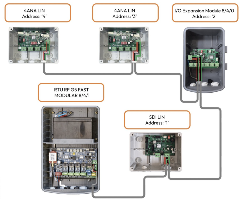
In G5 Fast, there is an option to connect several LIN cards in parallel. When connecting several LIN cards of the same type to the RTU Modular, set up a unique address for every LIN card. The RTU Modular automatically detects the LIN card type, and LIN card address, and transmits the LIN card type, address, and the LIN card Data to the Master unit.
4 ANA LIN Expansion Module:
Designed for high-resolution analog input, this expansion card reads up to 4 standard analog sensors (either 4–20 mA or 0–5 V).
- Resolution: 16-bit
- Configurable Parameters: Sampling rate, powering time, averaging, hysteresis, and more.
- Programming Tool: Workbench PC software

3x 4 ANA LIN Expansion Cards in Parallel - Customer Installation
4 ANA LIN Expansion - Installation & Wiring Instructions:

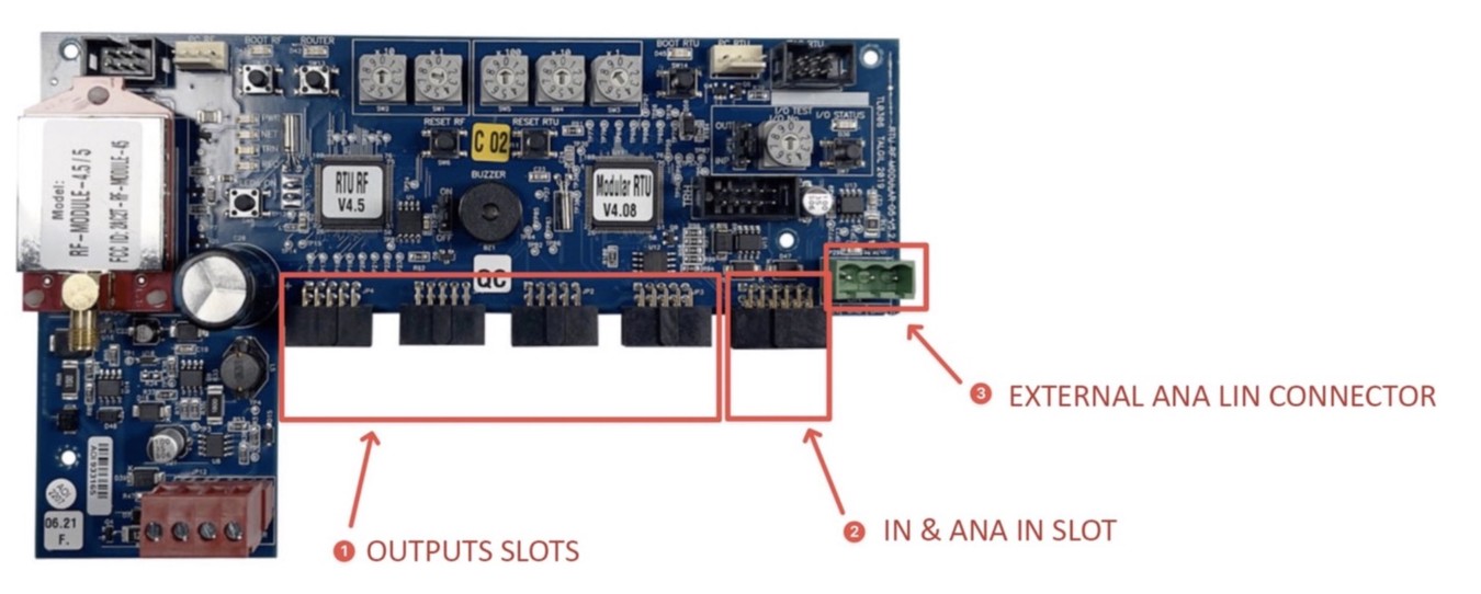
- Use the two dip switches called ADDRESS to set the 4 ANA LIN card address.
- Use the 4 dip switches to set up the Analog input types.
- When the Dip switch is 'OFF', the Analog input type is Voltage.
- When the Dip switch is ON, the Analog input type is Current.
For example, if Analog input 1 is Voltage (0-5V), put the dip switch 1 on V (turn OFF dip switch 1). If Analog input 2 is Current (4-20mA), put the dip switch 2 on mA (turn ON dip switch 2).
- Connect the Analog sensor wires to the Analog input terminal block. The Analog input terminal block has 3 screws. VS, AIN, and G where VS is the 12V DC power supply, AIN is an input for the Analog data (Analog Signal), and G is a Ground.
- Types of Analog sensors: Read the Analog sensor specification document or Datasheet to identify the Analog sensor type, Powering time, wiring, and the range. A Passive Analog sensor should be powered before reading the Analog value. It is also called excitation time. On the other hand, an Active Analog sensor should not be powered. To read a Passive analog sensor, If the Analog sensor has 2 wires, connect the Positive wire to VS and the negative wire to AIN.
- To read a Passive analog sensor, If the Analog sensor has 3 wires, connect the Powering wire to VS, the DATA (Signal) wire to AIN, and the Ground wire to G.
- To read an Active analog sensor, connect the DATA (Signal) wire to AIN, and the Ground wire to G. - Connect the LIN communication cable to the LIN port on the 4 ANA LIN card where 12V is a 12V DC power supply (Red), GND is the Ground (Black), and DATA is the LIN communication (Green).
- The maximum length of the LIN cable is 10 meters.
- Connect the LIN cable to the LIN port on the RTU Modular.
FOR MORE CONFIGURATION OPTIONS - Visit the Ordering Guide - RTU RF G5